New generation current sources for very low resistance measurements
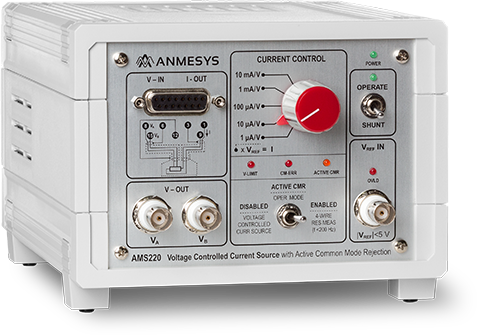
AMS220
Voltage Controlled Current Source with Active Common Mode Rejection
The only instrument on the market possessing the patented „active common mode rejection“ technology (U.S. #9,285,809, March 2016), dedicated for use with DAQ units and lock-in amplifiers
- Ensures active rejection of common mode voltage in resistance measurements.
- Allows routine measurements of very low resistances (less than 1 mΩ) even in the most demanding conditions (e.g. temperatures below 500 mK).
- Can operate as an external module of a lock-in amplifier to extend its functionality to that of an AC-resistance (impedance) bridge.
Troubles with very low resistance measurements?
Are you aware that four-wire (Kelvin) method is only necessary, but not sufficient condition to perform correct low resistance measurements? Artificial results may still occur because of errors due to common mode voltage.
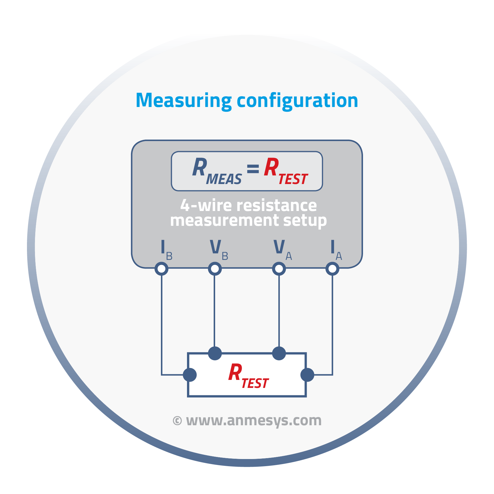
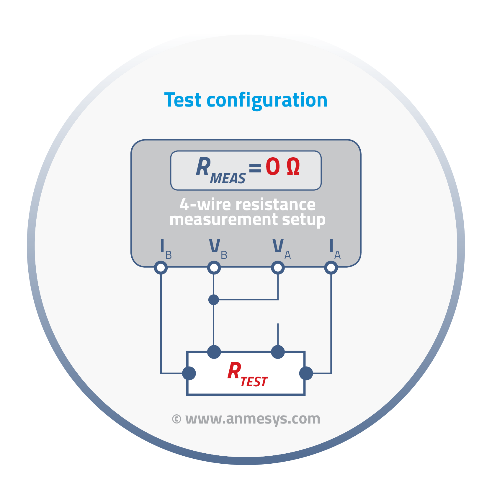
Test your four-wire resistance measurement setup for common mode errors!
As illustrated in the figure below, the four-wire resistance measurement setup in measuring configuration can be easily modified to test configuration* that must unconditionally provide ZERO resistance if measuring correctly.
Facts & Fundamental Questions concerning low resistance measurements
The four-wire (Kelvin) method itself is not a sufficient condition for measuring low resistance correctly!
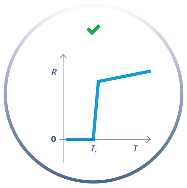
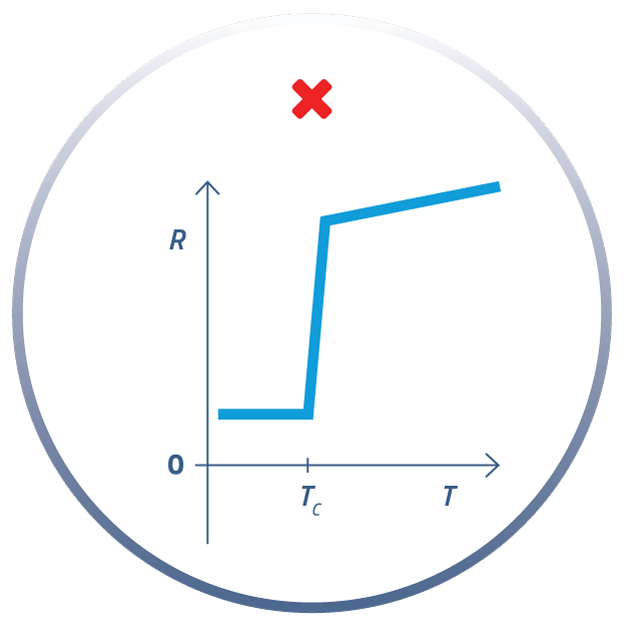
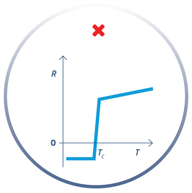
Typical symptoms of common mode errors in the four-wire resistance measurements
How to eliminate common mode errors in resistance measurements?
What is common mode voltage and differential amplifier common mode error?
How to detect common mode errors in resistance measurement setups?
Why CMRR or CMR is an important parameter of instruments?
Four-wire connection assures only “transmission” of the correct voltage difference (VD = V2 - V1) to the differential inputs of the voltage sensing instrument. However, if VD is very low in comparison to common mode voltage, VCM = (V2 + V1)/2, the measurement precision can be drastically degraded by common mode error.
The common mode error is proportional to common mode voltage and increases with decreasing Common Mode Rejection Ratio (CMRR) of the used voltage sensing instrument. (More info in Solutions.)
Measurements affected by common mode errors exhibit an “unexpected” setup dependent resistance contribution. As a rule, in presence of common mode errors, measurements of the same sample provide different results if
- performed in different apparatuses, or
- different instrument types and models are used for the resistance measurement at the same sample installation (i.e. the same cryostat and wiring), or
- different instruments of the same model are used for the resistance measurement at the same sample installation.
Considering relevancy of common mode errors, the observed “unexpected” resistance contribution is a function of resistances distributed in the branch of current leads, CMR parameter of the voltage sensing instrument, and properties of a unit used to force a test current through the sample. Therefore, different results as mentioned above can be a consequence of
- different resistances of segments in current path (including all contact resistances) if sample is installed in different apparatuses,
- different CMR parameters of different units used to voltage sensing. (Note that even for instruments of the same model the CMR varies from instrument to instrument),
- different type/architecture of current sources used for current excitation of the sample in different setups.
It should be noted that “accidentally” the contribution due to common mode errors can be equal in different setups; nevertheless, presence of common mode errors in a measurement setup can be detected by these tests.
Since common mode error is proportional to common-mode voltage, it will absent if common mode voltage will be suppressed sufficiently.
The AMS220 Voltage Controlled Current Source with Active Common Mode Rejection is able to eliminate common mode errors thanks to the patented technology (U.S. Patent #9,285,809; March 2016). Unlike conventional current sources, the AMS220 not only controls the current, but also monitors common mode voltage on the load and maintains it at negligible level. (More info in Solutions.)
To perform correct resistance measurements without common mode errors, the AMS220 in conjunction with a lock-in amplifier can be used instead of an AC resistance bridge. (More info in Solutions.)
To measure the voltage difference between two signals, VD = V2 - V1, differential voltage amplifiers are exploited. It is customary to consider an ideal case that the output signal of the differential amplifier is just the voltage difference of the signals applied to the amplifier inputs, amplified by differential gain GD, thus VOideal = GD (V2 - V1). However, the output of a real differential amplifier reflects also the “background” signal due to common mode voltage. The common mode voltage, VCM, represents the voltage level common to both inputs of the differential amplifier and is defined as an average of V1 and V2; VCM = (V2 + V1)/2.
The real amplifier output voltage is VO = GDVD + GCMVCM, where GCM is so called common mode gain and GCMVCM represents the differential amplifier common mode error. (More info in Solutions.)
If applying the same voltage signal (transferred by only one signal wire) to both differential inputs of a voltage sensing instrument, the correct measurement result must unconditionally correspond to the ZERO voltage difference at the instrument’s inputs.
Exploiting this fact, making only minor change in connection of signal wires/cables enables to detect presence of common mode errors even in already running experiment. For reliable evaluation of the experimental setup more complex tests to reveal presence of common mode errors are needed.
Common Mode Rejection (CMR) and Common Mode Rejection Ratio (CMRR) indicate how much of the common mode voltage will appear in the measurement. Insufficient capabilities of instruments to reject common mode voltage represents a serious limitation for measurements of very-low resistances, because (very much greater) resistances in the current path can easily cause common mode voltage several orders of magnitude greater than the sensed voltage difference. Nowadays technology limit is CMR≈140 dB or CMRR≈107 (i.e. amplification of the differential voltage across the amplifier inputs is 10 million times greater than the amplification of the common mode voltage). Typically the CMR varies between 80 dB (CMRR = 104) and 120 dB (CMRR = 106). An example how CMR of an instrument can affect result of (very) low resistance measurement can be found in Solutions.
About us

We focus on the research, development and production of specialized measuring instruments, with emphasis on those for very-low resistance measurements.
Up to now we are the only manufacturer utilizing the patented technology of active common mode rejection (U.S. Patent #9,285,809; March 2016).
Thanks to the patented technology our current sources with active common mode rejection (devoted preferably to lock-in amplifier users) enable reliable measurements of resistances down to very-low ones, even in the most demanding conditions.