How to identify common mode errors in resistance measurements
A simple test to identify common mode errors in four-wire resistance measurement can be done by modification of an original four-wire resistance measurement setup as shown in Fig. 1a to one from Fig. 1b. Because in this case both voltage inputs (VA, VB) sense the same electrical signal, the sensed voltage difference is zero, so the correct resistance measurement must unconditionally give a value of 0 Ω.
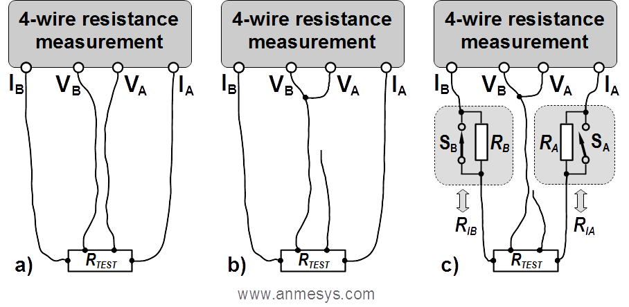 Fig. 1 Tests to identify common mode errors. Schematic depiction of the standard four-wire resistance measurement setup (a), its modification for the simplified test (b), and connection for the thorough test (c). When the purpose of the thorough test is to check a measuring instrument, without testing a complex wiring, the resistance under test can be replaced by a shortcut.
However, this simplified test yields information relevant only to the particular experimental conditions (particular load, specific temperature, etc.), but it does not necessarily reveal possible system weaknesses in all cases where the setup can be used. For example, it can be insufficient for systems where the resistance of current paths (i.e. resistance of current leads or contact resistances) vary significantly due to temperature changes. This simple test can also be conditionally ineffective when using so-called differential current sources. Differential current sources drive the load "symmetrically", i.e. voltage on their outputs IA and IB is of the same absolute value but of the opposite polarity. Thus, if both current branches have equal resistances, the common mode voltage is zero, and so the common mode error is also zero in this specific case. However, when this balance is broken, e.g. by different contact resistances, potentials of voltage signals sensed on the test resistance move towards the potential of the output connected with the branch of lower resistance, which results in a creation of the common mode voltage. This causes corresponding common mode error that increases with imbalance increase.
A thorough test can be performed using the connection shown in Fig. 1c., containing resistors that can be used to change the resistance of the electric current path by means of the switches SA and SB. Resistances (RA and RB) of these resistors should be comparable to resistances of current paths in a real experiment and should not be less than the estimated maximum resistance change of the current path that may occur in (different) experiments. Detailed inspection shall be performed by measuring all combinations possible to be created by the switches SA and SB. A properly measuring system must unconditionally provide a value of 0 Ω for any of these combinations. Fig. 2 shows examples (for two different types of utilized current sources) how the results of the test can look like if RA = RB = 10 Ω, and the CMR of the voltage sensing unit is 100 dB.
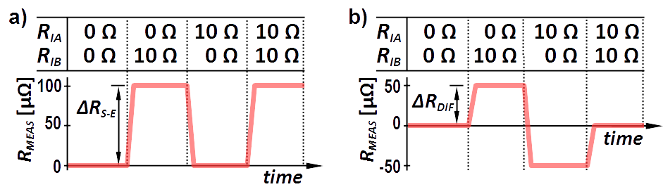 Fig. 2 Possible common mode errors in resistance measurement utilizing a single-ended (a) and a differential (b) current source. A settling time of an instrument/setup is represented by intervals between steady readings.
Results of the test as shown in Fig. 2 can be estimated for different CMR of an instrument*) using the table below if RA = RB = 10 Ω. Note that the higher the resistance values RA and RB, the higher the common mode errors.
| CMR [dB] | 80 | 90 | 100 | 110 | 120 | 130 | 140 |
| ΔRS-E [µΩ] | 1000 | 316 | 100 | 31.6 | 10 | 3.16 | 1 |
| ΔRDIF [µΩ] | 500 | 158 | 50 | 15.8 | 5 | 1.58 | 0.5 |