Simultaneous measurement of normal and the Hall resistance using the AMS220 and two lock-in amplifiers
The setup of a lock-in amplifier and the AMS220 in the functionality of an AC resistance (impedance) bridge can be extended by a second lock-in amplifier to perform simultaneous normal and the Hall resistance measurements, as shown in the Fig. 1.
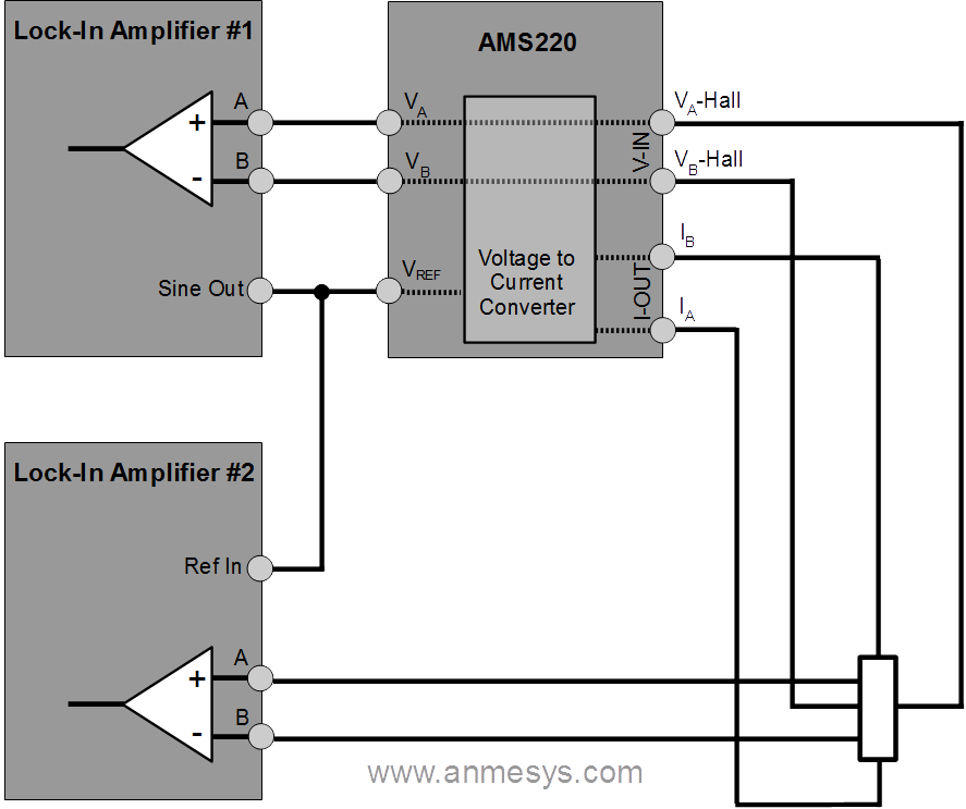 Fig. 1 The principal block diagram of the simultaneous measurement of normal and Hall resistance utilizing the AMS220 and two lock-in amplifiers.
As shown in the figure, the Hall voltage sensing is carried out by the “main” circuit with the AMS220. This is desirable mainly because the Hall voltage signals are usually less than signals on the sensor/sample in the direction of the current flow, so the control of voltage potential levels of sensed signals should be preferably optimized with regard to the measurement of the Hall voltage. The second lock-in amplifier (#2) should be configured for sensing signals with defined potential against the ground.
The reference voltage output of the first lock-in amplifier (Sine out) can be used as the reference signal for the second lock-in amplifier, as shown in the figure. Also, TTL synchronization output signal from the first lock-in amplifier can be favorably used for the purposes of phase-sensitive detection by the second lock-in amplifier.
Fig. 1 The principal block diagram of the simultaneous measurement of normal and the Hall resistance utilizing the AMS220 and two lock-in amplifiers.